Andoer M-12 monopod head jam

Andoer monopod head jamming up?

Andoer M-12 monopod head

Whilst waiting for a wimberly monopod head I needed something quick and cheap to allow me to use my monopod with larger lens/camera combinations. Now don’t get me wrong these Andoer heads are nothing like wimberly but I did at least expect it to get ,me out and taking photos. For most of my monopod work I just need to give the arms a break from the weight of the camera. I’m never going to let go of it, (that’s tripod territory) So I really just need a head that allows me to pivot the camera. For $20 the Andoer, which honestly looked like a clone of some “other” better known devices, should have provided such a simple requirement. TBH if it was made with just a little more attention to detail it would have.

The good news is if you have one that jams up like mine did, half an hour in the workshop and its certainly useable. Now those that follow me or have read other hacks and repairs will know I have access to a decent workshop but really this can be fixed with a file.


The sides are not square

The problem is that out of the mass produced mold the knuckle parts are not parallel sided, it doesn’t sit square.Which means as you pivot there is a good chance at some point its going to catch. The above image clearly shows the jam point and how off square the whole thing is.

not centred which jams the bolt head to one side.

The axis too is off, ie the hole through the unit is not central. This happens in a number of places. First the outer knuckle that houses the bolt head. The hole is not central to the hex indentation. I suspect during factory assembly, in mine at least, it was forced into position which caused the thrust washer to distort.

It also meant the inner knuckle was not horizontal. Not that it would have been anyway because the hole bored through the inner knuckle was not central either. Please note all these pivot tests were done with it completely loose, un tightened.

All we really need is a horizontal spindle.

Just a horizontal pivot and two ends to hold the shaft. Not rocket science.

After some machining we have faced the side so its square. You can see how bad the hole is and the alignment to centre is out.

It’s an axle Jim but not as we know it.

So now that that’s square it should pivot fine but we have lost some material in the process and as mentioned the original thrust washer was stuffed, we need a replacement. For this I used a mylar washer, I needed less than half a mm, Teflon would be nice but I couldn’t find my supply of scraps. A little bit of your favourite lubricant to both surfaces and away you go.. I generally don’t tighten or lock the spindle so no need to over engineer this bit for now.

As for the rest of it?

It’s fine, the QR Arca swiss is nicely machined and contains the safety screws.Knobs and such are fine. For $20 and some file work it will do the job I intended it for. Hold the weight of the camera while I wait for the bird to decide to take flight.

DSC_3119
the swan and I

Resurrect cheap speedlight mounts- Pt1

Cracked speedlight mounts? Let me show you a fix.

The typical online cheap speedlight mount, like the one here are made of very low quality plastic.

sppedlightmount_3

Cheap Speedlight mount repair

They tend to crack very easy if you tighten the stand lock . After trialling various glues which never held and a number of encapsulation techniques I decided this approach was the quickest and cheapest way to get these mounts back in my kit bag.

Two problems…

The first issue is the internal lock nut. They often don’t sit flush. The outside of the flanged nut is tapered and thus as you tighten, pulling the nut into its too small a hole, it begins to force the plastic apart. We need to ensure the forces are well and truly on the flange and not on the sides of the nut. Trying to machine out this hexagonal hole for a better fit would be almost impossible. However the plastic is a low temperature type.

Solution 1…

Unscrew the bolt and the nut often falls out. Using pliers and gripping the flange hold it over a heat source, hot air gun, hair dryer it really does not need much heat. Certainly don’t over heat it as it could melt too much into the plastic. With it nice n warm drop it into the hole(aligned with the old hex shape) and using its heat and your pliers push it home until the flange shoulder is hard up against the plastic.

sppedlightmount_1

Make sure the nut is flush

Cracked or not- fix no2…

Our second issue is the cracks or possibility of it cracking along the mould lines or pretty much anywhere. I have a number of these of varying type and all have cracked in different locations. Using a small round file add grooves to each corner.

sppedlightmount_2

Create grooves to hold the wire.

The grooves make it easy to keep the wraps of wire in place. You don’t want the the wire covering the openings(where the stand mounts). AWG25 seems about right. Plenty of strength and allows a little bit of stretch. Wrap the wire around 4 or so times. Get it good n taught, twist it off and then solder on each side to make it all one. Think of it aka a dentist tooth band. The crack is still there but we are stopping it from getting any worse. There is enough space top and bottom of the mount hole to put two bands.

Wrapped up…

That just about wraps it up. I have applied this hack to all my mounts now, those cracked and those yet to crack. These cheap mounts are not the best, they will hold a speedlight ok but add any modifier, umbrella or softbox and the weight is too much to bare. I would not recommend their purchase but if you are like me and started out that way, then you have probably collected quite a number of them. I hate to throw things out and this hack gives them a new lease of life.

Whats Next?…

Stay in touch for Part 2 of this exposè on speedlight mounts. Next up we will discuss why I have moved over to S-type/bowens mounts. But lets not throw these out just yet. I hacked these old E-Type mounts so the speedlight lays parallel to the umbrella pole just like an S-type.

Manfrotto 055 Pan Repair

Manfrotto MH055MO-Q6 Ball Head

I haven’t posted for a while due to just simply being busy but I think you will like this one.

I recently purchased a second hand Manfrotto MH055MO-Q6 Ball Head. I wont say where from and perhaps the “good price” should have triggered alarm bells. I took the bait, I was assured it was in good working “near new” condition. It was Manfrotto. What could go wrong with these robust and lovely engineered beasts?  It arrived in good time and the un opening indeed revealed a pretty unscratched, clean looking ball head. I put it through some basic tests and noticed the pan lock was weird and  not locking. I hadn’t touched one of these before and there is very little info in its “user manual” or on the net. So I was a little unsure. I put it aside, this was going to require more time.

Next day I spent 3 hours learning, discovering and researching this beast. Eventually we would have a happy ending but it took a few tears and anger management to get there. I’d like to point out here that I feel its a bit of a design flaw on Manfrotto side, perhaps its been addressed in the later revisions but the design does allow the user to get it wrong and potentially wreck it.

Pan-screwplate-burred

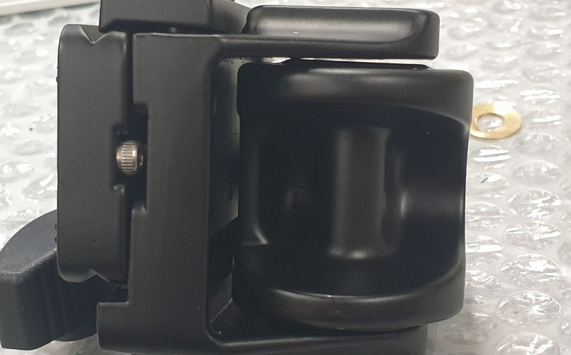
Pan plate screw thread

Tale of two pieces.

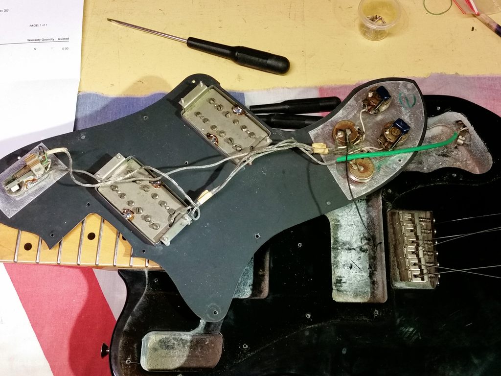
Lets get straight to the problem and then we will reverse engineer the solution. As you can see above this pan assembly screws up into the ball head. It’s all a little bit interactive. It sets some pretension on the ball head friction so you can’t just screw it all the way in, more on that later. As you can see in the picture the thread is burred and flattened. This is because the threaded plate has spun around and become out of sync with the pan lock pin. The lock pin should protrude through those holes and clamp on the black inner plate NOT the aluminium thread.

alignment

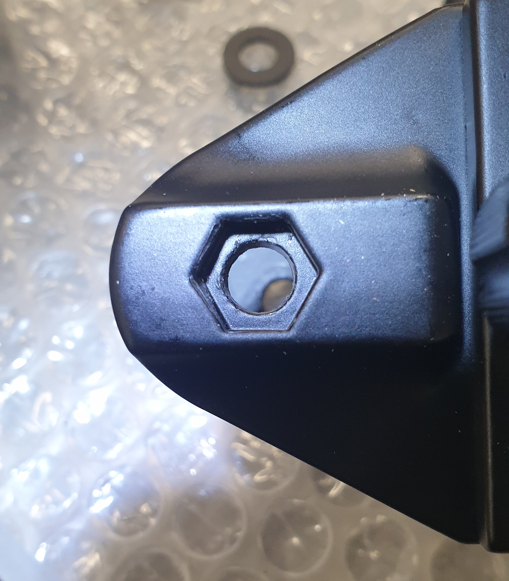
Pan lock pin alignment

If you remove the pan lock knob and its pin you should see this above. A clear hole through to the black plate. In my case all I could see was mushed silver thread. To be totally sure its correct. When you put the pin in it should almost be flush with the outside. If not something is stopping the pin going all the way in and it will grab and mush whatever is in its way.

alignment-pinin

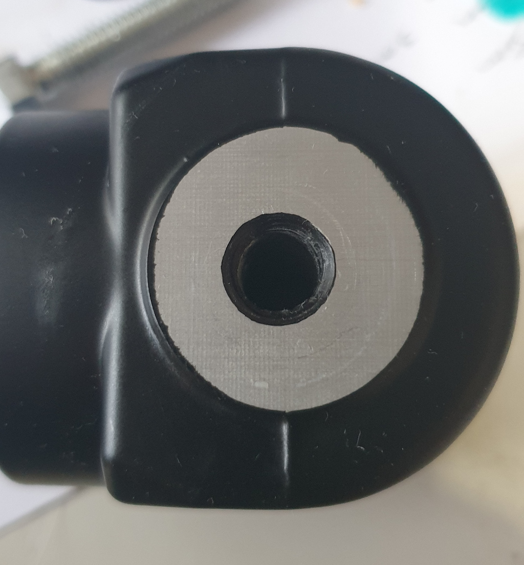
Pan lock pin pushed all the way in.

Lets dig a little deeper.

How it Works..

Disclaimer first. I am not a repair centre. All the information here was gleamed by pulling it apart and thinking it though. As a side note I did find a schematic (spare parts drawing) of similar heads here.

The pan assembly, once removed, consists of three parts. (right to left) the black pan base plate, the aluminium screw plate including the bearing or glide surface and a brass tension/lock ring. The lock ring holds the screw plate onto the black base plate. Looking closely at the brass ring you can see little circles. These are made by the friction or gap setting screws which come up thru the base plate. They stop the brass ring from sandwiching the screw plate to the base so tight that it wont spin/pan. Ill come back to that later. The screw plate simply sits on the base plate , where all that grease is and spins around it. In position, inside the ball head the screw plate does NOT move. It’s actually the black part that spins around. Or its the casing that spins around the stationary base plate which is screwed to the tripod. I guess that’s a Earth around the Sun or Sun around the Earth debate. I’ll leave for the flat earthers to decide.

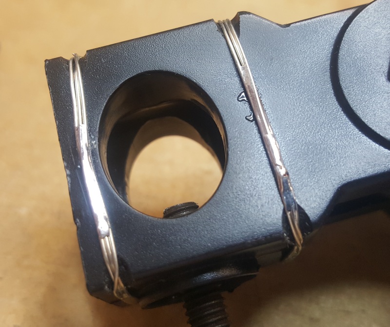
Pan plates separated.

In my case the lock pin was grabbing on the silver thread and locking that (whilst mushing the thread). This however still allowed the black plate to spin around and thus no pan lock.

The Repair

Was two fold. Repair the damage to the screw thread and then make sure everything was in alignment and the friction was correct across all the surfaces.

As mentioned above the brass ring sandwiches the screw plate to the base plate and with the aid of the set screws sets the friction of the pan. This is where some tooling up is required. In order to remove the pan assembly from the ball head and then the brass ring I had to make up a manfrotto spanner 🙂 Simply a bar of aluminium with appropriate spaced screws that line up with the dowel holes. Shown below is the brass ring end of the spanner.

DIY Manfrotto Spanner

This tool allows me to unscrew the brass ring from the base plate. I cleaned all mating surfaces or mushed aluminium dust and re greased. Re-assemble with just the right amount of pan friction. It shouldn’t wobble but should also not be too tight to spin around. Removal of the pan base from the head requires the other end of my spanner. Here I have a 3/8 hole so a bolt can lock it into the base(via tripod thread) Two 3mm screws thread through the spanner and into the two large dowel holes(left n right) and finally into the smaller holes in the silver screw plate. You may have to rotate things a bit to get this all to line up.  Note in the image below you can also see the black rubber ball (up n down)which normally sits snugly on top of the brass ring set screws. You will need to remove these to adjust the friction and if you are going to separate the brass ring from the assembly.

Removing the pan assembly from the head.

and this is the pan assembly end of the spanner. Ignore the left most hole it was in error and not used. The bolt holds the spanner to the base and the two screws must engage into the dowels on the silver screw plate. Its this plate, the inner aluminium that needs to be unscrewed. Note in my case as the thread was mushed this was a little bit hairy. I didn’t want to cause more problems to the already damaged thread. Take it easy, especially when putting it back in paying close attention not to cross thread it.

3/8 bolt and two 3mm screws to engage and allow unlocking of the thread plate.


Once removed I cleaned the screw thread very carefully with small needle files only where it was mushed and hope it wouldn’t derail on the way back in. When screwing the assembly back into the head don’t go all the way as that will apply pressure to the ball lock assembly. I pretty much went in till it stopped then unscrewed until the pan lock hole aligned with the screw thread plate hole as shown previously. This gave me a loose ball but still plenty of friction to lock it in position when required and allowed proper use of the pan lock system.

So here is the $100 flaw.

One may ask, “so what stops the silver plate from unscrewing when you pan the head”? I hope you are still with me and have followed to the end because this is the important part. Apart from the pan knob and lock pin there is nothing else. So if you do unscrew the knob ie loosen it way too much then swivel the pan it can become unaligned. Except for this one little old  grub screw I wonder what you do?

the grub screw

Hidden away almost under the ball lock knob is a small grub screw. If you are removing the base assembly this screw must be removed. It basically screws into the silver thread and locks it to the outer casing..ie stops it from unscrewing itself on the odd occasion someone has removed the pan knob and swivels the pan base. There is no indent or dowel hole and the grub is small compared to the mechanical advantage of the base so it does not provide this, after thought, of safety very well. Make sure you put it back in tho.

All Smiles.

The end result turned out ok. I avoided a financial disaster and possibly saved confrontation with a disreputable seller.  I also have to report the head lives up to its name. Ok it was perhaps abused by a muppet of a user but on the upside and in the hands of someone with even half an IQ point its a super solid robust bit of kit that will no doubt last a lifetime. Even after abuse and misuse Manfrotto lives on.

Pot gluck

de Fender never dies

Moons past they built stuff well. Time waits for no man however and will take its toll but with a little TLC, the life returns.

Fender tone pot not working or intermittent and in for repair. Many would replace with new conductive plastic pots or perhaps the last weeks thin carbon ones but just stop a minute! Smell the roses. These pots of yesteryear were built tough and thick, the carbon is in mm not microns. Sure they can crack or etch in but take the time to have a look before reaching for the new.

2017-05-22 18.07.01

pretty gunked up, corroded but don’t judge a book by its cover

Spray to save..warning

Many also would jump in with a squirt of electronic cleaner spray and rotating it a few times. Again I say take some time and look inside first. The spray may well clean it out but these twisters have moving parts and you stand a good chance of removing the gluck and the very necessary lubricant. 

A good rock song has only 4 tabs

Ok not the best headline callout, rock songs have 4 chords and tabs are used to convey guitar music..see the link? Fine I’ll move on. The pot has 4 tabs that can be prised open and allow the whole thing to come apart. No surprises inside to spring out across the shed or at least there shouldn’t be.

2017-05-22 09.58.41

naked pot, all revealed.

Shown halfway into the cleaning process. I used a brass wire brush to remove most of the metal work corrosion. WD40 or  electronic cleaner to remove the gluck. Either way a final rinse in electronic cleaner. The things to look out for are the track wipers and the track itself. If these are too worn we may be in trouble. without lube the shaft, wipers and track can deteriorate quickly.  If all is well we can continue. Then liberally smear dielectric(silicon) grease on every moving part yes including the carbon.  Put it all back together.

Log it?

One of the reasons to rejuvenate rather than replace is that guitar pots come in a few varieties. I am talking about resistance values but most importantly Log or Linear. Guitarists that love their axes tend to get used to that “sweet” spot on the dial. Subjective? maybe but these are passive setups. Load(which changes with pot position) can have an effect on the pups and thus change the sound. The less we change the less chance guitarist dude has to re adjust. The second reason is simply one of genuinity.

2017-05-15 18.50.33

note there is no wire from the tone pot cases.

So what didn’t work

For those interested apart from the gluck buildup on the pots the actual problem was one of intermittent tone control. The manufacture relied on the shielding foil to carry the earth(common) to the tone pots/capacitor configuration. Bad gluck was in there too between the pot and the foil. I wont rely on just a clean in this case and so additional wire from the main earth to the tone pot cases will insure it never happens again.

2017-05-15 18.45.37

Fender lives to play another day

Bolt of lightning

I don’t blog every repair I make

I just happened to get a good run of interesting ones lately. This bass amp from GK Gallien Krueger was transformed into a dead duck by a 10cent bolt. First of all they are a great amp. I was really impressed once I restored it to working order. The workmanship is A1 “mostly” see caveat below and for its size packs a powerful punch. Its an older amp, now superseded but after a little searching parts(from EFS Australia) are available and GK, EFS and Keen, answered emails promptly. All things that keep you felling warm n fuzzy. Even Keen Ocean, the manufacture of the toroidal transformer answered me and although no longer on the production run gave me the full specs.

It fizzed then nothing

Was the fault report and upon opening I found the toroidal loose. I buzzed thru a few things and while power was getting to the transformer primary there was nothing on the secondaries. At this point I had no info on the amp or toroidal and suspected a blown winding. On removal the reason was clear.

There is a screw which holds the handle to the top of the cabinet. Shown right. It protrudes the chassis plate, has eventually worn thru the rubber, the plastic and finally shorted the toroidal winding to the earth. Reminds me of those trees, that given time, just about will grow up through anything. You could pin this to manufacturing or design fault but lets not blame game and move on. Really, the rest of the quality is superb.

I ground down/ shortened the bolt, this wont happen again. Thought did come to mind as to how many other out there are waiting to be discovered.

2017-05-15 17.47.19

Bolt below the chassis line, no protrusions now.

Meaner to service

I always give things a label or rating on their service ability. Like the failure, in this case I am in two minds. Amp comes away from the cabinet with 4 screws and one connector. Front and rear panel, should you need to , come away with 6 more. But remove the main board from the chassis? oh dear minefield territory. You see the numerous transistors are wonderfully screwed to the chassis which doubles as the heatsink. But the numerous transistors legs poke up through the PCB. In other words you have to desolder them all  and remove the screws to get the PCB out, just to look under for burnt tracks. And with the PCB loose you cant power up and run it to trace the signal path.

No ping, error 2

I buzzed the transformer in circuit to try and ascertain what winding had cooked. It didn’t make logic. Please note I had at this juncture made a rookies mistake. I assumed it was working once or that nuthing or no one had touched it since then. But this was not true, user had played and the transformer wires were not returned to original positions. I chased a few herrings down before enlightenment dawned.2017-05-13 16.43.23

I unwound all the plastic, unwound the first layer of secondary, there was a slight nick in the enamel coating but no meltdown as I expected. I buzzed the transformer again and all looked good, time for the variac. Wound the 240 up slowly and the secondariness came up perfect, no shorted turns here. Hit it with the mega for an isolation test, for good measure.

2017-05-14 11.48.52

Unwinding the mylar tape, miles n miles of it, layer upon layer upon layer

With just a slight nick in the enamel I went for a smear of epoxy just to be sure and began the long re winding of the plastic, mumetal and plastic, plastic, mylar, plastic, you get the drift.

2017-05-15 17.50.56

Good as new, rewound

Sound check

So back into circuit. Since the unwinding, the email responses I had sent to GK, EFS and Ocean had rolled in. Specs on the transformer and the “correct” PCB pinout of the windings. All now made sense, silly me.

2017-05-15 17.55.36

Ready to rock

Ready to pump it…or not

Turn on , measure power rails all good. Guitar plugged in and …and…..nuthing. hmm volume up, gain up, check check.  This combo amp has like an external speaker output. It also has a internal/external switch tee hee. Push that home and away we went.

And like WOW for a little puppy she sure can belt it out. Great tone too.2017-05-15 18.12.19

Played a bit, soak tested it etc etc the usual and she is ready to sing for another gig. I don’t often make an attachment to repairs but I was sorry to see her glide out of the shop. Very tempted to offer to purchase myself but how many amps can you play at the same time…at volume 11 🙂

Bread n butter

Teac A-3340S

Love getting this old stuff in for repair, so many memories and for some back in the music industry of the 70s this was their bread n butter knife. Classic example of great workmanship and quality. 40 years on and still kicking goals.

All my old band stuff is on reel to reel

Said the customer. Id like to use this again to dump em to my hard drive, (tascam usb digital recorder), Cubase it all back up to scratch.

2017-05-13 12.31.25

Drive belt

Belts are tough

Drive belts can be one of two things tough or flexible. The latter being the required attribute in this instance. The former being what happens to em after a years in the shed.

2017-05-13 12.21.23

Reel counter belt

Life is never step a after step b, things happen along the way.

Remove the back mesh panel.Spool off, remove 3 screws and the wooden side plate. Allows you to reach the grub screws holding the counter pulley.

Next trick is a length of wire to hook down and flip the belt over the lower counter pulley. Hangon!!…New belt is too long. No missed idler wheel in this setup so they sent us the wrong belt. Return the old belt to its home and use the undo.

The drive belt on the other hand was a little smaller than expected, the old ones don’t stretch that much. Too short we can deal with tho and this was the main symptom of the problems so we continued with the install.

Manuals for this Teac A3340 are available on the net so just follow the instructions. Again using  a piece of hook wire you slip the new belt over the pulley. Make sure the 50 or 60hz gotcha dont trip you up. The pulley has two sizes…read the manual.

Ma heads all clogged up

I always take a poke around other known problems with these machines. First port of call struck gold. Well brown gunk anyway.

2017-05-13 12.05.16

Good access allows easy clean of the heads

Spent a bit of time cleaning the moving and non moving bits. Wear was visible but they should last long enough to dump a few reels of music.

2017-05-13 13.19.35

the beast

Love em like fine silver these old dudes and this one is in great nick. Oh the stories they could tell and retell and retell and…..


Little boxes

The on going process of recovery and recycle

with a bit of, hi tech new age thrown in, hit another upper today.

2016-11-23-09-55-06

Pick a size, select an arrangement..custom built

I’d scored some old index card tray units and thought they would be perfect for housing screws and electronic components. I just needed “lots” of individual containers. I thought and looked at various options, from plastic to metal but eventually recognised that they were also about to throw out a filing cabinet full of folders…think card. Think card, extrapolate, think boxes hmm.

2016-11-23-10-11-21

Box design, holds itself together

So I whipped up a box pattern and headed off to the laser cutter..Ok so not everyone has a laser cutter and I admit that while I could, ie its possible to cut by hand I wasn’t about to waste that much time.. enter hi tech weaponry, I love the Rayjet!

2016-11-23-12-27-04

Rayjet doing its thing

The Pattern

was pretty straight forward, I made one from paper first then just increased a few tolerances to care for the the card thickness. the ends fold in and fold over while the tab, which pokes through the bottom slit, holds it all together.

2016-11-23-10-12-43

Folding

Folding

next up and using a steel ruler off the edge of a table was simple enough. Mind you the laser was cutting three  to my one folded completion. Part of the design used the slits n cuts to help me align the ruler so there was no need for a print or drawn fold lines stage.

2016-11-23-12-27-22

Soldiers standing in a row. Cut quicker than I could fold.

Sizes

With the template created in Coreldraw it was easy to resize to create various boxes and easy enough to calculate so they fitted in snug.

2016-11-23-09-55-06

Rearrange able 

I made about 4 different sizes, extra long, medium and small that are “plug n play to fit the tray”.

Problem

There are 16 of these trays per cabinet,depending on the boxes size, anywhere from 6 to 20 odd per tray. Anyone care to help me fold?

Blogged in response to a mate who reckons I’m always building something interesting and should blog more about it.

Toothless repair

3d plastic printer to the rescue

A bit of animitronics gear came into the workshop the other day. Disassembling the gearbox revealed a toothless gear. This gearbox was under a bit of load and it was the design that lead to its demise.But before I get onto the modifications I still had to replace the gear or was this going to be one of those retro fit a new gearbox jobs?

to print or not to print

The left side gear looked to be of a standard drive gear so I focused my attention on the double decker.

Gear-brkn_web

Gear on the left is cracked, gear on the right is detoothed.

After chasing, surfing and devouring the web I found no supplier of this rather strange sized gear. It was a “double decker” and the sizes just did not seem to match anything. A friend said “3d print it” but I was pretty sure the ones I had access too did not have the resolve to get this sort of detail. I also know the laminated like construction does no bode well for strength. Being a learner at Solidworks cad, I thought it would be a good project to attempt to at least model it anyway so I pursued the idea. A couple of online tutorials later and I had a decent 3d model.

wSpur-dble_bs

Off to the printer

As expected the resolution was a problem. Not knowing much about gears I was pretty sure it simply would not mesh nicely. I was somewhat mistaken.

3dprint_crpd

Old above new below

As you can see no nice edges, all a little bit rounded but it did seem to mesh fairly well. Then I broke it… 😦

Almost exactly in the same spot as the original.

Let’s take a closer look at the gearbox

As I said its under a fair bit of load. The motor is turned on for a set amount of time which turns the final output shaft about 140 degrees. When the motor turns off a spring system returns the output shaft and thus unwinds all the gears including the motor. An interesting concept. Problem is there is no safety cutout or mechanical clutch if the motor keeps going or if for some reason the shaft does not return fully and thus becomes out of sync and possibly driven past the 140deg point. It literally relies on the motor stalling. All  well n good if the gears can take the load. But in this case things were against it.

alignment_err

Gear only drives the top 1/4 thus reducing surface area contact/strength

The output shaft(top gear) is only driven by the top 1/4 of the other, thus reducing surface area contact/strength. This can easily overload the top and tear the tooth.

gbox_mod_web

Gear position is now higher

The position of the gear after the mod. Originally it was riding on the base plate. Plastic spacers moved it higher up the shaft. So it was now engaging the entire spline length. Having learnt the lesson and solved the cause I printed another gear.

alignment_btr.JPG

Lots more surface area to distribute the load

One thing leads to another

Of course that was the easy bit. The problem now was the housing and mounts were all too thick. I had to trim some plastic away to make room for the elevated output gear. With this complete is was back to another test….So far so good. I really do expect the 3d gear to break tho but the point was its now working and hopefully without too many , beyond the 140 degree travel excursions, it might last